Smart Move Modes and Settings
A number of command modes are available to the user while using the Smart Move tool to change the behavior of the Smart Move command. All the modes are key-in driven and can be executed while the Smart Move command is active.
Key-in Configuration
These key-ins can be configured to individual mouse button assignments using the Button Assignments configuration dialog or alternatively the key-ins can be assigned to function keys using the Function Keys configuration dialog. See the MicroStation documentation for details.

Single Mode - Before you accept a feature selection, the following key-in can be executed to toggle in and out of Single Mode. When Single Mode is active, only the selected feature is loaded into the Smart Move tree view upon its selection. All related features are ignored when populating the tree view in this mode.
• Xfmstdutiladdin smartmove single
After a feature is selected (and before a final location is accepted), Smart Move can operate in several different modification modes. While the selected features are manipulated, the following key-ins can be executed to toggle in and out of each mode:
• Xfmstdutiladdin smartmove align
• Xfmstdutiladdin smartmove rotate
• Xfmstdutiladdin smartmove spin
• Xfmstdutiladdin smartmove suspend
- Align - Aligns the feature to closest geometry as the cursor moves.
- Rotate - Rotates the feature around the Accudraw compass. Note: The compass can be moved to any location.
- Spin - Rotates the feature around its origin.
- Suspend - Suspends the dynamic display of feature manipulations to allow the user to perform other tasks such as zoom or pan.
Construction Geometry mode is sometimes required to precisely and accurately align or offset a layout relative to existing features or geographic geometries. Temporary linear geometries can be created while the Smart Move command is active. The geometries are automatically removed when the command exists or restarts.
The following key-in can be used to toggle in and out of Construction Geometry mode:
• xfmstdutiladdin smartmove construct
While the Smart Move command is active:
- Enter Construction Geometry mode by executing the key-in.
- Select a linear feature or geometry to use as a template to generate construction geometry from. The construction geometry dynamically appears on the cursor. Right-Click to reject the selection and load the next geometry template at the pick location.
- Drag the temporary construction geometry to the desired location.
- Use the left mouse click to accept the construction geometry location.
- Repeat steps 2 through 4 to add additional construction geometries.
- Exit Construction Geometry mode by executing the key-in again.
Feature Manipulation Settings
Each feature in the tree view has a toggle that can be used to enable or disable manipulation of the feature. If a feature is toggled off, all features below that feature are also toggled off.
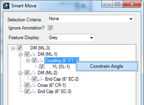
Constrain Angle setting is available for point node features related to linear features at an attachment node point (between the linear features start and end nodes). It allows the user to lock the angle of linear features starting or ending at the point node feature.
These feature are identified by an additional icon beside the check box in the tree view.
 Constrained locks the angle of the linear feature related at the next lower level in the tree. The point feature remains at the intersection of the two related linear features.
 Not Constrained maintains the relative location at which features connect.